a. General requirements An oil drain port should be provided at the lowest point of the line. Compensators should be used at appropriate locations in the pipeline. Add pumping oil valves should have interlock function. Cleaning requirements Parts shall be cleaned prior to assembly. After assembly, tanks and piping systems should be cleaned with clean aviation fuel.b. Pressure requirements Before assembling the piping parts, hydrostatic test should be carried out, and the test pressure should be 1.5 times of the rated working pressure of the pump, and the pressure should be maintained for 5 min without any damage or leakage. The refueling system works normally under the rated working pressure of the fuel pump, and there is no damage, malfunction or leakage under the condition of 1.25 times of the rated working pressure of the fuel pump. Aircraft pressure refueling fittings with regulators are installed at the end of the hose for end-of-hose pressure control. An in-line pressure control valve and venturi are installed in the piping after the pump for in-line pressure control. If the pressure at the venturi is higher than (0.35+0.035)MPa, the in-line pressure control valve should be closed to prevent overpressurization. When refueling at the rated refueling flow rate, if the aircraft fuel tank is closed in (1~2) s, the water strike pressure of the piping system should not exceed 0.84 MPa, and should not exceed 0.42 MPa after 15 s. When the pressure control valve is opened by operating the Dynaudic control valve to perform refueling, the flow rate should rise from zero to the rated flow rate in (10~15) s, and the closure time should be (3~5) s, and the over flow rate after closure should not exceed 200 L. The closure time should not exceed 200 L. The refueling operation should be closed in (1~5) s, and the in-line pressure control valve should be closed to prevent over-pressure. After the refueling operation is completed and the refueling fittings are reset, the pressure in the pipeline should be maintained at (0.1~0.15) MPa.
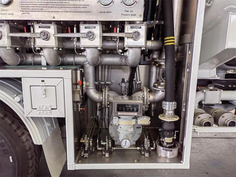
c. Component requirements Oil pumps and drives Oil pump selection of the main performance parameters in line with the performance requirements of the refueling system centrifugal pump; the use of engine power, through the car transmission, power take-off drive oil pump, should be a smooth drive, reliable, easy maintenance. Filtration Separator The filter separator meets GB/T 21358 or API 1581 technical requirements. The flow range and pressure rating should meet the requirements of the refueling system. Horizontal structure is selected, with the end cover opening facing the outside of the vehicle, and pivot type end cover and return type bolts are adopted. The upper part is equipped with manual and automatic exhaust valves, safety valves and peep sights. The exhaust port should be connected to the oil tank inlet and outlet pipelines with oil testing sampling port and direct-reading differential pressure gauge or differential pressure gauge. Self-resetting valve should be set on the discharge pipeline, and the discharge port should be equipped with joints and protective cover, and the location should be convenient for operation. Set up a closed-circuit sampler to take samples from the inlet and outlet of the filter separator, and the oil from the sampler is discharged into the oil collecting tank; the oil collecting tank is equipped with a liquid level display and a breathing valve, and the bottom of the tank should have an oil discharge port with a self-resetting valve. flowmeter a) Suitable for measuring the flow of aviation fuel; b) Measurement accuracy class not less than 0.2; c) The measuring range meets the requirements of the system; d) Capable of batch, cumulative and instantaneous measurements; e) Zeroing function for batch measurement. Hose Reels Able to neatly wind a specified length of refueling hose. The pressure refueling reel is mechanically retracted and manually unwound. The reel works reliably, facilitates the unwinding and winding of the fueling hose, and the time for unwinding and winding should not exceed 1 min and is adjustable. A hose reel braking device is provided to prevent the reel from rotating when the vehicle is in motion. The refueling hose is made of conductive hose in accordance with GB 10543 or API 1529. Aircraft Pressure Fueling Fittings Meets the requirements of HB 6122, HB 6130 or SAE AS5877 with a voltage regulator installed.
4: Safety interlocks
The refueling truck is equipped with a safety interlock function, and the vehicle enters the braking state in the following states: a) Pickup gearing; b) The refueling hose was not retrieved; c) The platform or guardrail is raised; d) Bottom oil fitting not disengaged; e) Static grounding cable not retracted; f) Aircraft fuel cap not reset; g) Failure to carry out security confirmation. In the driver's cab to facilitate the observation of the set of interlocking point indicator light, interlocking state red indicator light, reset indicator light off. The cab is fitted with a master safety interlock indicator, which is yellow in color. The cab is equipped with an overrun safety interlock device, which is capable of being sealed, and the overrun indicator light is red in color.
5:Manipulators and Instruments
1 Provide a Dudermann control valve operating handle on the operating surface. The Dudermann control valve shall be equipped with an override function and an activation of the time indication, and the override device shall be capable of being sealed. The Dudermann control valve can be operated from a distance of 15 m from the operating surface by means of the operating handle.
2 The operating surface sets the hand throttle of the engine.
3 The operating surface is fitted with a locking emergency engine shut-off button, red in color, with visible markings.
4 The driver's cab is equipped with an extractor maneuvering device.
5. Set up the instrument panel on the operation surface for easy observation. Install the pump inlet pressure gauge, outlet pressure gauge, venturi pressure gauge, hydraulic pressure gauge, and the calibration connector of each instrument on the instrument panel.
6 The maneuvering devices are safe, reliable and flexible. Colors and coatings The color and coating shall comply with the provisions of QC/T 484. Logos and descriptions Product labeling should comply with GB/T 13306 and GB/T 18411. Installation of operation instruction boards and refueling system process flow diagrams at easily observable places on the operation surface. Clearly display the grade of aviation fuel on the refueling truck. Valves, instruments and operating devices are marked with their name or number of the signage, and with the operation of the instruction plate, instruction manuals etc. are consistent. The sign is fixed in a conspicuous position on the vehicle. Quality of assembly Finished products and parts do not material defects and machining defects that affect use, reliability, function, handling, appearance, or safety. Parts are not loose, deformed or damaged. Maneuvering room, piping and tanks are clean and free of foreign matter. Oil, gas and electrical lines are neatly installed and securely fastened.